5V vs 3.3V: Which is better for Arduino? Logic level and operating voltage for Beginners
When working with Arduino Microcontrollers or Raspberry Pi boards, which voltage should you use your components? What is the difference between logic level and operating voltage? Let's walk through a beginner's guide to voltage levels in arduino projects.
Intro
If you work with electronics, be it microcontrollers like an Arduino Nano or SBCs (single board computer) like a Raspberry Pi, you've surely noticed that there is more than one voltage level marked on these boards. Usually, you'll see 5 volts and 3.3 volts (also marked 3V3 in schematics) indicated somewhere on these boards.
When I first started working with these, I didn't really understand why it mattered and kind of just decided, "I'll just use all 5V and pretend 3.3V doesn't exist." I very soon found out that I couldn't just ignore 3.3V. With this guide I'll try to help describe for beginners why operating voltage and logic levels matter, and how you can decide which to incorporate in your project.
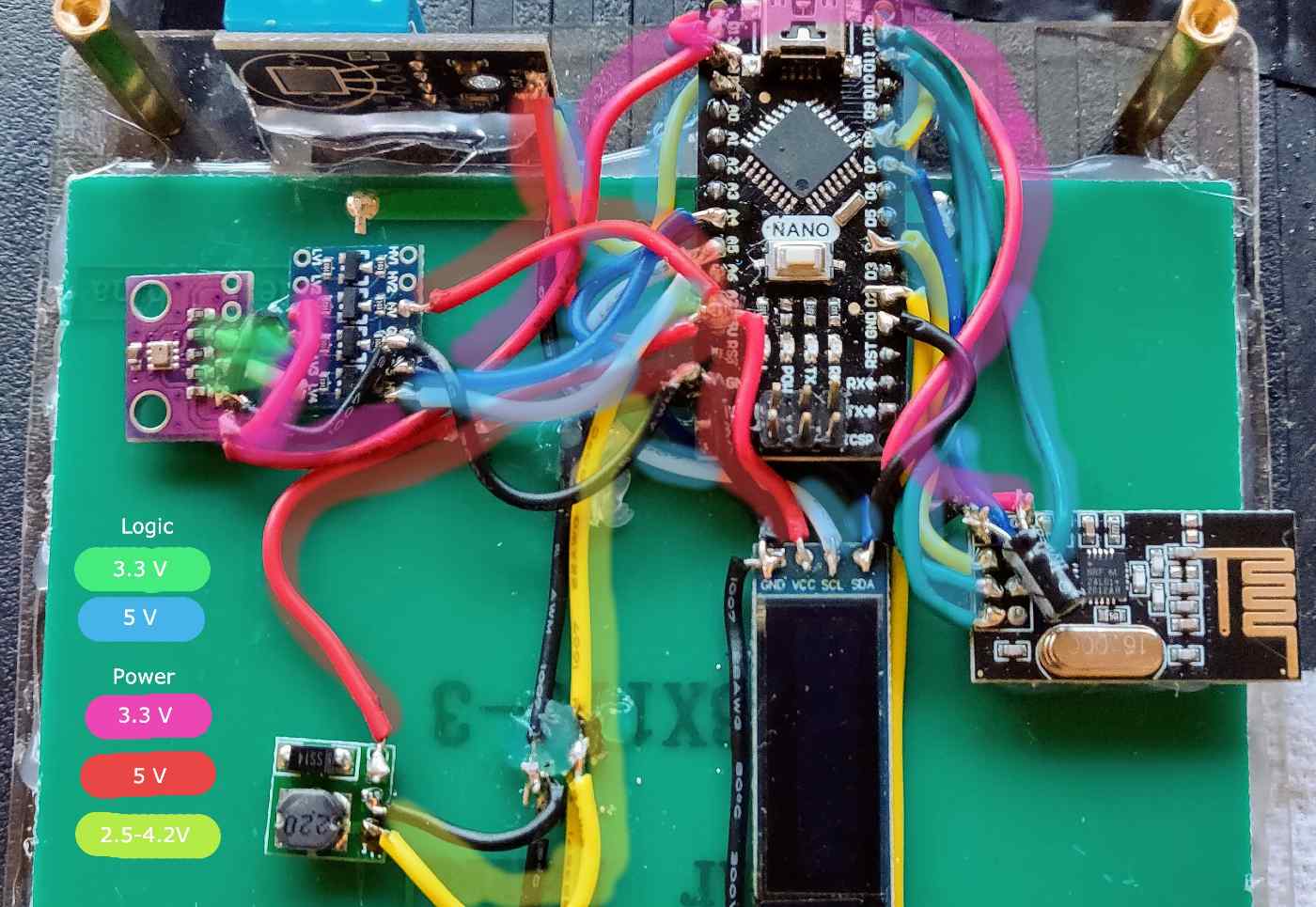
Power and Logic Voltage LevelsInput voltage and operating voltage (power)
A device or component might have a rated input voltage, which is the range of voltages the device will be able to successfully take and use to power all of its components. Sometimes this might be pegged to a particular number if there is no way to regulate the voltage. In other cases, like the Arduino "VIN" pin, it might be a large range, since there is a circuit that allows input from 7-12V since it will be converted (stepped down) to lower voltages for the device.
Operating voltage refers to the actual voltage (or range) a component expects to operate at. For the Atmega328P chip used in the Arduino Nano application, that would be 5v. This means that in order to function "as intended" it must be powered with a stable 5V DC.
You might be wondering why the minimum input voltage for the VIN pin (6-7V) on an Arduino nano would higher than the operating voltage (5V) on the device. That can be explained here:
Arduino Nano VIN and 5V regulator circuitNotice that the Arduino Nano VIN is not directly connected to the Atmega328P chip, rather it is connected to the input of an LM1117 5V regulator IC, which can be seen on the bottom of the Arduino Nano board.
If you have a look at page 6 of the LM1117 datasheet, you'll find that a design using it must account for a ~1-1.5V dropout voltage. With a Vin <6V, the output voltage is not guaranteed to be a stable 5V. Your board would likely still power on in this case, as the Atmega328p can run on a pretty wide range of voltages, but for the Arduino Nano application specifically, you are asking your trouble. That is (mostly) because of logic levels!
Logic levels (signal)
Note: here we cover digital signals, not analog signals
In contrast with input and operating voltage, logic level voltage is important not for how we deliver power to different components in a system, but for how different components in a system communicate with each other.
When I first started making stuff with Arduinos, I had no concept of how electronics talk to each other in a physical sense - I had been a software developer for years, built plenty of computers and played around with electronics, but frankly had no idea. What does it actually mean for one device to send a signal to another?
Electronics communicate with each other digitally by setting the voltage on a wire that connects two or more devices to HIGH or LOW. You might ask yourself, what makes a signal HIGH or LOW? That is a question that we are empowered to answer when designing a circuit. All components that need to send signals to each other need to speak the same "language" in terms of logic level signals. For the purposes of this guide we'll say there are two options: "3.3V Language" and the "5V Language." In reality, these logic levels are standardized according to the proportion of signal voltage to the supply voltage.
| Technology | LOW voltage | HIGH voltage | Notes |
|---|---|---|---|
| CMOS | 0 V to 1/3 VDD | 2/3 VDD to VDD | VDD = supply voltage |
| TTL | 0 V to 0.8 V | 2 V to VCC | VCC = 5 V ±10% |
An example: a logic-level lightbulb switch
Say you had a component that is intended to act as a switch to turn on and off a light bulb. It has a 12V supply input - always ready to supply 12 volts and plenty of power to the lightbulb. It will also have a signal input that will determine whether the lightbulb should be powered by the 12V supply, or turned off.
Here is what the schematic might look like:
Logic level switch exampleFor our purposes, we decide this switch speaks the "5V Language." This means that it has some way of detecting (like a tiny voltmeter inside the component) what the voltage is on the signal input. If it is LOW, the lightbulb does not get any 12V power. If it is HIGH, it gets the power and lights up. In the above diagram, you could imagine that the 5V Logic voltage source is an Arduino with a digital output in connected to the SIG input of the switch.
Because electronic devices operate in the physical world, the "5V Language" of signals needs to have some range so it can tolerate slight variations in signal voltage. For that reason, we decide this lightbulb switch considers anything from 4V-5V to be HIGH and anything 1V to 0V to be LOW.
If your Arduino nano's Atmega328p processor is getting a clean, stable 5V, it will be able to accurately output a 5V signal to turn on your lightbulb every time. If, however, your Arduino only had 3.3V available to it, say because you plugged a 5V battery into the VIN pin, it might have an issue switching the lightbulb on and off, or it might cause it to flicker randomly.
Lots of devices have a higher tolerance range and might still work even if the signal wasn't reaching the full logic voltage - but it is completely unpredictable when designing a new circuit - so it is best to make sure that all your components are speaking the same "language" when it comes to logic level signals.
My Arduino has a 3.3v and 5v pin, is it compatible with both logic levels?
Arduino Nano PinoutLooking at the Arduino Nano pinout shown above, there is certainly a 3.3 V pin present on the board (usually written 3V3 on schematic diagrams). While this is true, the Arduino Nano (and most Arduino boards that operate at 5V) are NOT compatible with 3.3V logic levels.
The 3V3 pin on an Arduino is simply a small 3.3V power source that can be used to power additional components in your system. The onboard USB IC that allows the Arduino to interface with a USB port on your computer has an integrated 3.3V voltage regulator which has the 5V pin as an input:
Arduino Nano USB chip with integrated 3.3 V regulatorNote the regulator (inside the tiny little USB chip) in the block diagram from the FT232R datasheet.
As we discussed previously, if you supplied the VIN pin of the Arduino Nano with less than the minimum (7V) voltage, the problem seen on the 5V pin would cascade down to the 3.3V pin, which itself would have a voltage lower than 3.3V.
If you supplied the 5V pin with 5V directly, the 3.3V pin would have no problem, as expected, since the voltage regulator inside the FT232R chip would get its expected 5V input, and everyone will be happy.
In short - the 3.3V pin is for powering external components, and does not indicate that the Arduino itself will simply work with 3.3V components - there are definitely ways to make that work, which we'll discuss later in this guide!
What difference does the voltage level make?
So, 'til now we've established that there are different "languages" or logic levels that electronic devices use to talk to each other, and different input voltages and operating voltages that are used to power them. What is the difference? Is more voltage better for microcontrollers? Is low voltage better for battery powered devices? Let's find out!
Power Consumption
When it comes to power consumption, low voltage is king – for the most part. In an ideal world if you were powering a device with a little battery around 3 volts, you are probably way better off with 3.3V logic levels than 5V, as you likely wouldn't need to waste precious energy boosting up your battery voltage to properly power your components.
On the other hand, if you were making a low power device that required 5V to power a certain component, like a motor or a light, that might be a good case to opt for 5V logic level microcontroller. Why? If you'll absolutely need 5V for your supply voltage, and then insert 3.3V into your design, you will then require an additional voltage regulator to step down your voltage. Where possible, it's good to be able to keep the amount of step up/step down DC conversion to a minimum to avoid wasting huge percentages of power to inefficiency (there is no such thing as a 100% efficient voltage regulator).
Keep in mind that while there are methods of saving power in Arduino code or using external switching devices, it is often not easy to lower power consumption by 20-40%. Removing an unnecessary voltage regulator from your circuit can do just that.
Compatibility with microcontrollers and ICs
Keeping in mind that this is a hobby and not everyone has tons of microcontrollers and components around, you might choose to go with a certain operating voltage or logic level voltage based on the components you have on hand. That is absolutely fine - just make sure to keep in mind the tradeoffs and you can always improve on them in a future iteration on your design.
Power components
This one is mainly about MOSFETs. If you are not familiar with MOSFETs, I recommend this video (there are many more good ones on YouTube).
A MOSFET might be a really good example of that switch we talked about earlier with the lightbulb example. With an n-channel MOSFET, a positive voltage is required between the gate and source to "turn on" the MOSFET and allow current to flow between the drain and source.
You might be designing a circuit that involves an n-channel MOSFET with a gate to source threshold voltage of 5V (the voltage differential required to turn the MOSFET "on"). In that case, a supply voltage of 3.3V wouldn't be enough to fully switch power using that particular MOSFET without any additional circuitry. That brings us to the final consideration:
Simplicity
In some cases, you might value keeping the circuit simpler and with less parts even if it's not the most efficient or performant. That's fine too.
Mixing Voltages in a Single Project
With all this being said, it is certainly possible and common to mix different supply voltage and signal voltage in the same system. This is accomplished by two classes of components, respectively:
DC-DC convertors and regulators
5 V Boost ConvertorDC-DC convertors take a supply voltage and convert it to one that is higher or lower than the original one. In the photo above, a tiny 5V boost convertor is stepping up a lithium-ion battery voltage (2.5-4.2V) to 5V.
If we wanted to step-down the voltage to a lower voltage, a buck convertor could be used. This is a really versatile buck convertor I use in a lot of projects in terms of its size and input/output range.
As we discussed previously, linear regulators like the LM1117 also step-down voltage but are less efficient, and dissipate excess energy as heat, and usually have lower maximum power output.
Logic level convertors
3.3v-5v Bi-directional logic convertorWe mentioned before that it was possible to use 3.3V logic level components with a 5V microcontroller. This can be achieved using a pretty cheap and available component called a logic level convertor, like this 4 channel bi-directional 5V to 3.3V convertor.
This little component employs MOSFETs and 2 different supply voltages to "convert" a signal from "5v Language" to "3.3V Language" and vice-versa. What is actually happening is, on the 3.3V side, a 3.3V logic signal switches ON a MOSFET on the 5V supply side to put the 5V supply voltage on that channel's pin.
An important thing to remember about logic level convertors is that they are not actually stepping up or down voltage. They are simply switching on or off 2 different supply voltages. This means that you still need both a 3.3V and 5V supply voltage in order to use such a device.
Hope this guide was helpful to you, please give me a shout out on Twitter if you have any comments, questions, or things you think I should add/edit here.