DIY Gigabit 802.3at PoE+ Splitter: Schematic and Build Guide
Making a 802.3at Power over Ethernet (PoE+) splitter using through-hole components and a controller IC. Schematic and build guide - this is a great way to learn about how Power over Ethernet powered devices (PDs) work.
This post is part of a series on PoE (power-over-ethernet), see the first two posts here:
In this guide, we are taking the concept one step further by using "smart" PoE, by using the 802.3at standard to negotiate the level of power we want from the PoE switch. Read more about 802.3at specification here.
SAFETY WARNING:
PoE+ specification means this project will see voltages above 50V. This can be extremely dangerous. Do NOT undertake this if you are not experienced working with higher voltages and take adequate safety measures.
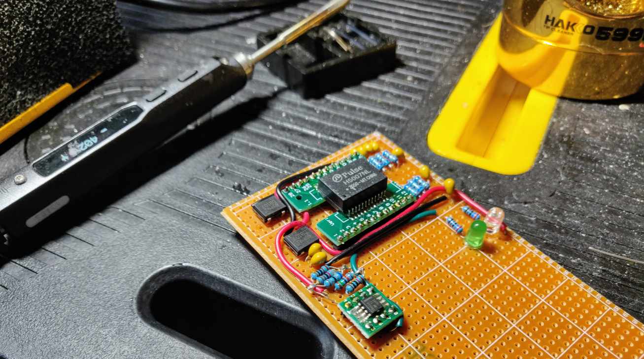
Here is a sneak peak at what the splitter looks like when the circuit is mostly assembled:
Assembled in a polycarbonate plastic enclosure w/ a DC-DC convertorComponents/tools used
Before we get into the build guide, here is a list of components used in the process. Keep in mind that my resistor kit did not have exact values for termination (75 ohms) or R(CLS) and R(DEN) resistors, so I had to improvise those by combining in series/parallel.
- Soldering iron, lead-free solder, fume extractor, flux
- Hot-air rework gun - this is optional, but makes it a bit easier to cleanly solder the SMD ICs
- Crenova Multimeter
- Spare CAT5 Ethernet cable
- Mikrotik CRS328-24P-4S+RM 24 port PoE switch
- Irwin wire stripping tool
- H6062NL pulse transformer
- TPS2379 PoE+ PD controller IC
- 2x DB107 bridge rectifiers
- Surface mount adapters cut to size (need to use something with SOP footprint and at least 24 pins) for the H6062NL and the TPS2379
- Perf board - I usually use this set but you can use any type you have, as long as you can solder through-hole components to one side
- Resistor kit
- Ceramic capacitor kit
- Green LED from this kit
- 47 microfarad capacitor rated to >100V (I pulled a 4.7microfarad off an AC/DC convertor I had since I don't have any spare 47 microfarad caps rated more than 50V)
Build Guide
OK, so let's get started. Below you'll find a schematic that maps out the overall design. I created a PCB board design that you can check out as well here. Keep in mind I haven't tested the PCB yet, I ordered a few pieces and will try it out and update. If anyone is interested in me sending over a board, please let me know on twitter.
Schematic
802.3at PoE+ splitter Schematic
The schematic is divided into 3 main parts:
- Top-left: ethernet transformer connections to ethernet cable IN terminals and ethernet OUT terminal
- Top-right: termination of cable-side and device-side center taps (for more about this, see the previous post about building a passive gigabit PoE splitter)
- Bottom: power over ethernet control and switch circuit
Ethernet transformer
Ethernet Transformer on SMD breakout boardFirst thing I did was solder the ethernet transformer to an SMD breakout board. If you have a hot air rework station, you can do this with hot air, or solder the SMD IC using a regular soldering iron, as I've covered in a previous post.
The above photo is of an H5007NL transformer as opposed to H6062NL mentioned in the parts list - I accidentally grabbed the wrong transformer at first and later replaced it - you'll remember from the previous post that you want to use an ethernet transformer that is rated for PoE, like the H6062NL.
Power from the cable-side center taps
DB107 Full Bridge Rectifiers added to boardWith the ethernet transformer soldered and attached to the perf-board, we can add the DB107 full bridge rectifiers. These will allow us to safely get power from either set of twisted pairs, and give us reverse polarity protection just in case a given PSE (power source equipment, like a PoE switch) has its positive and negative pairs reversed.
Connect center taps on cable side to rectifier inputsOne rectifier's input pins are connected to MCT1/MCT2 and another is connected to MCT3/MCT4 pins of the transformer. The rectifiers +/- output pins are connected in parallel and form the VDD and GND that will be used in our circuit.
Center tap termination
Now comes the center tap termination. In all honesty this is the part that I understand the least. I believe this has to do with minimizing noise and losses to the ethernet data signals. I have read some blog posts about studies saying in many cases it makes no difference. In any event, I decided to include it in my design as most ethernet circuits I've seen include it.
Termination of cable-side center tapsThe cable side is terminated using "Bob Smith Termination" with 10 nanofarad capacitors and 75 ohm resistors in series, all connected in parallel to a 1 nanofarad capacitor in series with "chassis ground." I am still a bit fuzzy on the concept of chassis ground in a splitter device that itself is just in between an ethernet cable and an actual powered device, but following other schematics, I have made it a relatively large area of conductor (in the perf-board case just a bunch of solder on a copper trace), connected to ground through a 1 nanofarad capacitor, as can be seen in the schematic.
Termination on device sideThe device side center tap termination is similar, but with the series capacitors omitted. Please note that I used 68 ohm resistors since I didn't have any 75 ohm resistors available.
Connect center taps to termination caps/resistorsFinally, the center taps can be connected to the capacitors/resistors per the schematic.
Soldering the TPS2379 PoE controller IC
Now it's time to turn to the brain of this design, the TPS2379. This comes in an SOP-8 SMD package, but there is a catch. It has a "power pad" on the bottom, which means it will not fit the standard SOP-8 SMD adapter breakout board that I have.
I decided to work around this by trying to solder the power pad and GND pin together using a tiny piece of wire, which didn't look pretty:
Soldering power pad and connecting to GND pinAfter creating that monstrosity, I had to further improvise to get the bump attached to the breakout board and avoid short circuits. I covered the power pad with a tiny piece of electrical tape, put it on the IC and added lots of solder to bridge the pins to the traces on the board:
Getting the raised IC connected to the breakout boardAgain, it is NOT pretty by any stretch of the imagination. But hey, it worked! The PCB boards I'm having made will eliminate this issue anyway.
802.3at PoE+ detection circuit
Now it is time to add the resistors that will allow us to get our desired power level negotiated with our PSE device. First is the detection resistor:
Connect TPS2379 and detection resistorAccording to the datasheet (page 16, "Detection" paragraph), a 24.9k resistor from VDD to the RDEN pin will draw a small current that will let the PSE know that this is a Power over Ethernet device requesting power. This is one half of the equation - next, we need to move on the classification.
Classification according to the PoE+ specification is done with a resistor from the CLS pin to GND, and is determined by a table provided in the datasheet (page 11):
Class Resistor SelectionFor this design, I went with Class 4, which calls for a 63.4 ohm resistor to ground.
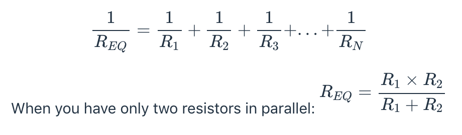
Connect classification resistor (RCLS)I didn't have either of these exact resistor values on-hand, so I combined resistors in series/parallel to achieve the desired amount. You can calculate these values based on resistors you have by adding the values together (for series connection), or using this formula for parallel connection:
Final connections/testing
Now that the PoE control circuit is finished, we can complete the final connections.
An LED for PoE negotiation status is connected with its anode to VDD and GND (through a 3.3kohm resistor) to the T2P pin on the TPS2379.
For power output, use the 47microfarad (rated for >100V!) capacitor connected in parallel between VDD and RTN pin of the TPS2379. This is important, as this is the drain of the internal MOSFET switch. If you connect directly to GND, you will not have any of the short circuit, temperature, or overcurrent protection the IC provides.
Connect cable-side twisted pairs to transformer Finally, the device-side ethernet data cable can be connected. The ethernet pairs should simply mirror those that were connected on the cable side. Take care not to solder the wires to the center tap pins.
Testing using a dummy load
I tested here using a dummy load I bought on Amazon. I don't really want to recommend this one as the voltmeter accuracy on here is nowhere near their claimed .01V resolution, it is actually .08V resolution. In any case, it is very useful for load testing high voltages like those of PoE.
Using the dummy load, I was able to successfully trigger the overcurrent protection of the circuit and draw 25.5 watts in a stable fashion.
With ethernet cables taped upHere is the device taped up to look a little neater. In the future I plan to add an integrated buck convertor.
Add LED, bulk capacitor and output wiresPCB Design for 802.3at PoE+ circuitHere is the PCB design I created for this circuit. I ordered a few manufactured boards. If anyone is interested in one to try the build, please follow me on twitter and give me a shout out.
Please note that I only link products that I have bought and tested myself, and some of the links above are Amazon affiliate links, which I earn a commission from (at no additional cost to the buyer).